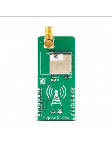


The device is a fully integrated single-chip transceiver intended for use in an industrial
environment.
The device incorporates several commonly used building blocks including a crystal
stabilized oscillator, a fractional-N-based phase-locked loop (PLL) for accurate frequency
selection in both TX and RX, Low Noise Amplifier (LNA), attenuator for Automatic Gain
Control (AGC), I/Q down-mixer and two high-resolution Analog to Digital Converters
(ADC). The conversion into the digital domain is done in an early phase, enabling a
software defined radio like approach
.
By transforming signals in the digital domain in an early phase, one highly configurable
RX channel is available including channel mixer, channel filter, ASK/FSK demodulator,
clock-data recovery, bit processor and a microcontroller memory interface (DMA)
allowing the microcontroller to complete the data handling and handshaking.
The device has an embedded RISC microcontroller optimized for high performance and
low power as well as an EROM for customer applications. The device also includes a
medium power UHF transmit system with a high dynamic range of - 35 to +14 dBm which
makes it ideal for the use in narrowband communication systems. The TX system allows
transmission with data rates up to 400 kbit/s NRZ.
Power ramping and splatter avoidance filters are included to ensure that the transmit
spectrum fulfills all the common standards in Europe, USA, and Asia. The phase noise of
the transmitter supports ARIB operation.
The device includes a series of timers to allow for autonomous polling and wake-up
applications. The TX and RX data buffers are located in the RAM with autonomous
direct memory access (DMA), reducing the 'real-time' overhead for the accompanying
microcontroller. The device can be interfaced via SPI, UART, or LIN protocol compatible
UART. Simplified programming of the device is facilitated by the HAL (Hardware
Abstraction Layer).
The transceiver is configured to operate with low active and standby power consumption,
ideal for battery powered applications.
| Type | Sigfox,Sub-1 GHz Transceievers |
| Applications | SigFox click offers connectivity to the SigFox network. It can be used for a wide range of IoT applications, which require large area coverage, such as the agriculture industry applications, parking lot applications, goods tracking applications, and similar |
| On-board modules | SN 10-13 Sigfox certified module, by InnoComm |
| Radio Region | Japan |
| Key Features | Official Sigfox network certified module onboard, simplified software functions allow rapid development, robust IoT networking with very wide area coverage, Sigfox cloud allows access to distant base stations and nodes, and more |
| Interface | SPI |
| Compatibility | mikroBUS |
| Click board size | L (57.15 x 25.4 mm) |
| Input Voltage | 3.3V |
This table shows how the pinout on SigFox 3 click corresponds to the pinout on the mikroBUS™ socket (the latter shown in the two middle columns).
| Label | Name | Description |
|---|---|---|
| PWR | PWR | Power LED indicator |
| ANT | ANT | SMA antenna connector |
We provide a demo application for SigFox 3 Click on our Libstock page, as well as a demo application (example), developed using MikroElektronika compilers. The demo can run on all the main MikroElektronika development boards.
Library Description
The library contains basic functions for controlling the click board.
Key functions:
int32_t sigfox3_init() - Function for initializing the sensor.int32_t sigfox3_wakeUp() - Function for waking up the sensor from the sleep mode.int32_t sigfox3_sleep() - Function for placing sigfox to the low power mode.Example description
Click board wakes up from sleep. Some tests are performed. After the tests and after the data has been sent and received from the network the click board is placed into the sleep mode to its low power mode. All events that are executed inside of the application task are printed to the serial port.
void applicationTask()
{
 char spiFrameACK = 0;
 char rData[20];
 uint8_t sendPayload[12] = "Test msg";

 _status = sigfox3_wakeUp();
 if(_status == _SIGFOX3_STATUS_SUCCESS)
 {
 mikrobus_logWrite("Wakeup succesfull",_LOG_LINE);
 _status = sigfox3_testSpicon(&spiFrameACK);
 if(spiFrameACK == 1)
 {
 mikrobus_logWrite("SPI test finished succesfully",_LOG_LINE);
 mikrobus_logWrite("Sending data to sigfox network",_LOG_LINE);
 _status = sigfox3_receiveMessage(&sendPayload[0],&rData[0]);
 if(_status == _SIGFOX3_STATUS_SUCCESS)
 {
 mikrobus_logWrite("Data received",_LOG_LINE);
 mikrobus_logWrite(&rData[0],_LOG_LINE);
 }
 else
 {
 mikrobus_logWrite("Network error",_LOG_LINE);
 }
 }
 else
 {
 mikrobus_logWrite("Error in echo frame",_LOG_LINE);
 }
 }
 else
 {
 mikrobus_logWrite("Error in wakeup",_LOG_LINE);
 }
 _status = sigfox3_sleep();
 if(_status == _SIGFOX3_STATUS_SUCCESS)
 {
 mikrobus_logWrite("Sleep entered",_LOG_LINE);
 }
 else
 {
 mikrobus_logWrite("Error entering sleep",_LOG_LINE);
 }
 Delay_ms(5000);

}
The full application code, and ready to use projects can be found on our Libstock page.
Other MikroElektronika libraries used in the example:
Depending on the development board you are using, you may need USB UART click, USB UART 2 click or RS232 click to connect to your PC, for development systems with no UART to USB interface available on the board. The terminal available in all MikroElektronika compilers, or any other terminal application of your choice, can be used to read the message.
You might also like