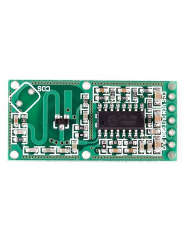


This sensor module has been designed as an alternative to the common PIR motion sensors widely used in burglar alarms and security lights. Like the PIR sensor, this sensor also detects only movements within its detection range. But instead of sniffing the black body radiation from a moving person, this sensor uses a “microwave Doppler radar” technique to detect moving objects. It has a sensitivity range of ~7 meters. When triggered, its TTL-level output (OUT) pin will switch from LOW (0 V) to HIGH (3.3 V) for a finite time (2 to 3 s) before returning to its idle (LOW) state.
Key features:
Supply Voltage: 4–28 VDC (tested with 5 V at my lab)
Operating frequency: ~3.2 GHz (observed by me at my lab)
Transmit power: 20 mW (typical)/30 mW (max)
Sensing Distance: 5–7 m (>3 m measured at my lab)
Pinouts:
CDS — Sensor disable input (low = disable)
VIN — 4- to 28-V DC supply input
OUT — HIGH (3.3 V) motion detected/LOW (0 V) idle
GND — Ground/0 V
3V3 — Regulated DC output (100 mA max)
This flexible sensor module can easily be used in conjunction with many microcontrollers and even without a microcontroller at all. It can handle power supply inputs anywhere from 4 to 28 V. The output pin can be utilized for a multitude of tasks, such as for driving an aural/visual indicator or even linking with the I/O of any 3-V microcontroller for further processing. During construction, avoid any metal part in front of the sensor module. Similarly, always keep a minimum of 1-cm clear space in the front and rear side of the module.
The low frequncy part
The core of the low frequncy signal processing is an IC marked RCWL-9196. The schematic says (in chinese) that it's similar to a BISS0001 PIR IC. But there are differences. Unfortunately I can't find any hard information (eg datasheet) on this. Nor can I find any information on the brand/company name "RCWL".
| Pin number | BISS0001 | RCWL-9196 |
|---|---|---|
| 1 | A Retriggerable & non-retriggerable mode select (A=1 : re-triggerable) | 3.3V regulated output (100mA max?) |
| 2 | VO Detector output pin (active high) | same |
| 3 | RR1 Output pulse width control (Tx) | same? |
| 4 | RC1 Output pulse width control (Tx) | same? |
| 5 | RC2 Trigger inhibit control (Ti) | same? |
| 6 | RR2 Trigger inhibit control (Ti) | same? |
| 7 | Vss Ground | same |
| 8 | VRF RESET & voltage reference input (Normally high. Low=reset) | Vin (4 - 28V) |
| 9 | VC Trigger disable input (VC > 0.2Vdd=enable; Vc < 0.2Vdd =disabled) | same |
| 10 | IB Op-amp input bias current setting | ? |
| 11 | Vdd Supply voltage | 3.3V regulated output (again?) |
| 12 | 2OUT 2nd stage Op-amp output | same |
| 13 | 2IN- 2nd stage Op-amp inverting input | same |
| 14 | 1IN+ 1st stage Op-amp non-inverting input | same |
| 15 | 1IN- 1st stage Op-amp inverting input | same |
| 16 | 1OUT 1st stage Op-amp output | same |
On the back of the board (the side without components) are pads for 3 optional components (0805 dimensions).
| Pad | Function |
|---|---|
| C-TM | Regulate the repeat trigger time. The default (unpopulated) time is 2s. A SMD capacitor to extend the repeat trigger time. Pin 3 of the IC emits a frequency (f), and the tigger time in seconds is given by (1/f) * 32678 |
| R-GN | The default detection range is 7m, adding a 1M resistor reduces it to 5m |
| R-CDS | the VCC is in parrel connection with CDS(RCWL-9196 pin 9) through R-CDS. Connect the LDR at the R-CDS to turn off the detecting function at night. (?? TODO: make sense of this) |
I started with an example Colpitt circuit [9] and substituted the 2N3904 NPN with a MMBR941 (Spice model from [10]). I am using the Windows LTSpice from Linear Technologies (available as free download [11], also works with Linux under Wine emulator). See colpitt.asc for a working Colpitt oscillator and rcwl-0516.asc for a model of the RCWL-0516 (however it does not oscillate!).
Vous aimerez aussi